LARC UHF Repeater Build
A long time coming
Our story starts in the beginning of November 2025. This write-up ended up being a little longer than I originally expected, but getting the club’s UHF repeater back on the air was not a quick one-evening job. It took troubleshooting, planning, parts from a few different places, and a good bit of teamwork. In the end, though, it was well worth it. The new LARC UHF repeater is on the air at 443.850+ MHz with a 107.2 Hz PL tone.
Testing 1, 2, 3…
It was dead. Our Yaesu DR-1X dual band VHF/UHF repeater was no longer repeating. A member of our repeater committee, Scott (KB2TRQ) had been on the repeater earlier in the week, so we knew that it had just happened recently.
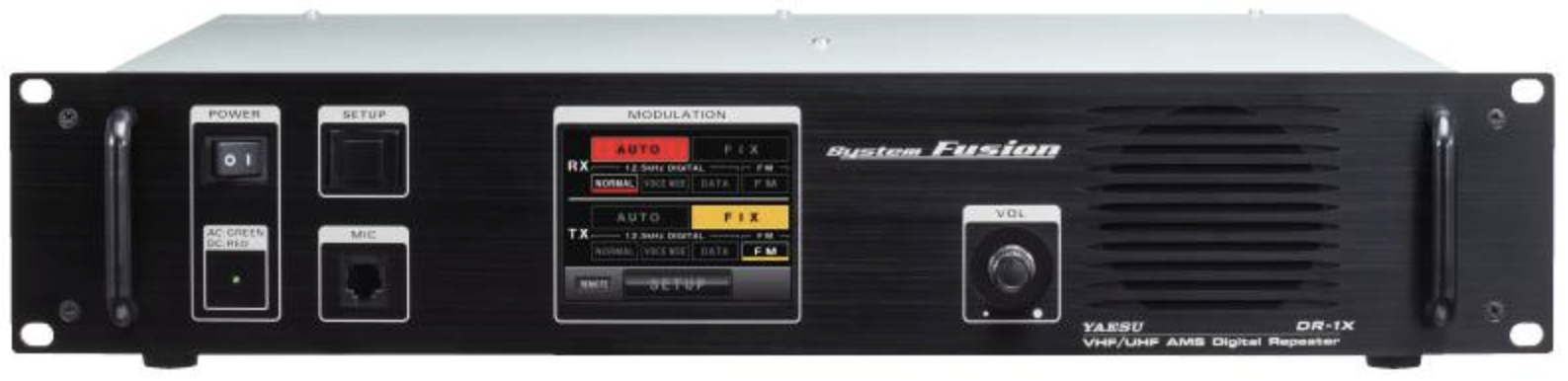
So the troubleshooting began. I started out by removing the DC power backup from the repeater so that we could do a full power cycle. I removed the AC power and waited for the display to start up. When the display did not show up, I grabbed the manual, which was luckily nearby.
I flipped through the manual and found that there was a way to get the display to turn on if had been disabled. I tried that and still it didn’t look like anything was happening. It was time to bring out the big guns - the factory reset. I flipped to the page in the manual, did the reset procedure and held my breath, hoping this repeater would come back to life.
But alas, it did not.
Now I have multiple thoughts running through my head. Was the repeater actually getting power? Just because the power led was lit up, didn’t mean that the components were getting power. So I un-racked the repeater and headed to the repair room.
Performing an autopsy…
A quick inspection showed no tamper seals that would void the warranty on the device (although it had long gone out of warranty). I grabbed a screwdriver and started removing the screws that held the cover on. Interestingly, they had no blue Loc-Tite on them. Once I had the cover removed, came the first internal troubleshooting test - the sniff test. No odor of burnt out components was obvious (IYKYK!).
I wasn’t sure where to go from here. John (KW2JR) suggested checking to make sure that the components were getting power from the power supply. Not being very versed in this level of troubleshooting, I started tracing out wires and plugs to see where they started and ended. Our club VP Dave (KD2PMU) had walked in and grabbed a multimeter and helped me start trouble shooting the power connections. This actually turned out to be easier to do than I thought. Plug the repeater in, turn it on, disconnect a connection, measure for voltage.
So we disconnect the power connector from the exciter, measure the voltage, 13.8VDC on the money. Time to check the receiver, same thing, 13.8VDC. So we knew that the radios were getting power. Just to be doubly sure, Dave and I measured the voltage coming off the power supply as well. We measured 13.8VDC out on the side that the 110VAC power was coming in on. Now we checked the DC backup side. The measurement came out as expected, 0VDC, as we didn’t have a DC power source hooked up. Everywhere we checked, we received the expected voltages.
“She’s dead Jim”…
At this point we were convinced that the main computer board, the “brains” of the repeater had decided that it was going to take an extended lunch and not return to the office. With nothing left that we could do, I unplugged the repeater, replaced the cover and screws, and with a heavy heart, placed the repeater on desk in the repeater room.
What future did the repeater hold? Dave suggested we reach out to Yaesu and find out an approximate cost to replace the controller board and bench fees. I remarked that it probably not worth the spend. Perhaps we could put it out on the club sale shelf and sell it to someone as a parts only repeater. The option nobody wanted to talk about, because it meant that we felt that there was no coming back for that repeater, was to dispose of it as e-waste. Any way you looked at it, we were now without a 70cm repeater. No more C4FM, no more WIRES-X, no more analog.
Rising from the ashes…
Ok, so maybe the whole “no more C4FM, no more WIRES-X, no more analog” was a little dramatic. We had been looking at some statistics and already knew that not many people were taking advantage of the analog side, much less the C4FM and WIRES-X. What we (the repeater team) knew was that we needed to get something on the air.
So Ed (W2GUT) came to the rescue. He had a repeater built from a pair of Motorola CM300 UHF radios with a Y-cable going to a small PCB which allowed it to act as a repeater. It was a great stop gap measure, but had a couple of deficiencies - namely that it couldn’t ID every ten minutes like it was supposed to. That could be figured out later, we weren’t planning on keeping it long term, just a bandage. Tim (N2LCJ) helped Ed get his radios onto the right frequencies and they went into the rack. We once again had a presence on the air! Or so we thought. Due to programming issues, sadly we weren’t able to get the CDM300’s on the air.
At this point we have a massive email thread going on among the repeater team. Scott mentioned that Tim had a stockpile of UHF Kenwood and Motorola radios, it would just be a matter of picking the right pair of radios. Steve (AG2AA) has now picked up the reins on the project and has put together a punch list of things that need to be completed.
- Select radios - Scott was leaning towards the pair of Kenwood TK-8180 UHF mobiles as they could be programmed from any version of Windows, unlike Motorola, which at best would require Windows XP and a RIB board.
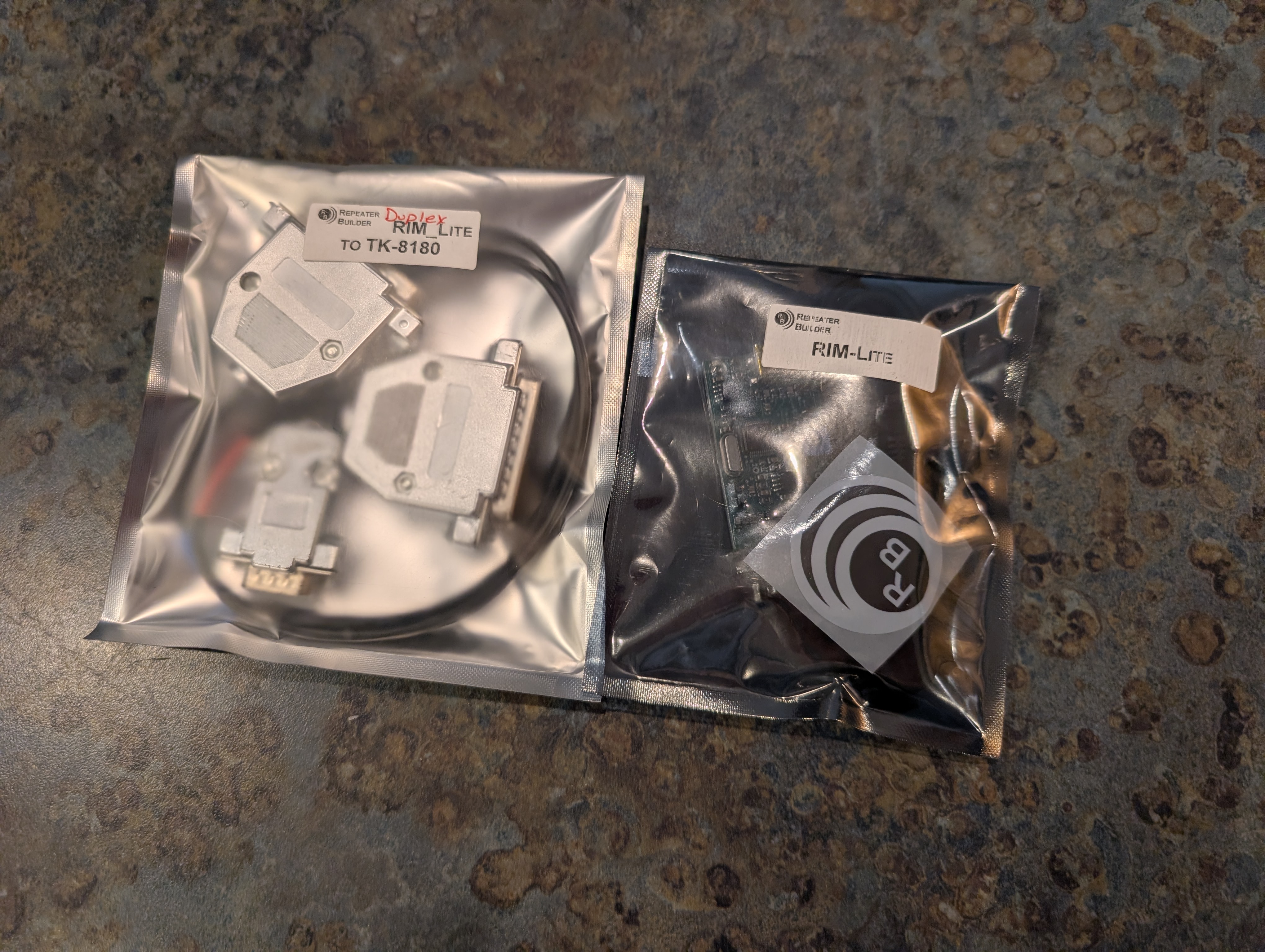
- Select an interface - Steve suggessted we get a RIM Lite device. The board is a dead simple interface, and they have the DB-25 Y-cable to DB-9 for interfacing the radios to the board.
- Add a controller - Steve had wanted to use a Raspberry Pi like we had on our 2m and 1.25m machine. I let the group know that I had a spare Raspberry Pi 4B sitting in my desk drawer doing nothing. I said it would not take much time to image and configure.
We now had a plan and a direction to move in.
“It’s alive!”…
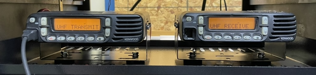
And so, our merry band of repeater technicians went about their tasks on bringing up a new repeater using the Kenwood TK-8180 radio pair. Scott took some time to clean up the repeater room some, and made all new jumper cables to go from the duplexer to the receiver and the exciter. While Scott was taking care of the grunt work, Steve had found the right RIM Lite controller and splitter cable for the radios and got them ordered. In practically no time he had the parts and sent an email saying, “I got the stuff!”
In the meantime, I had downloaded the latest HamVoIP image and got ready to build out the controller. I managed to get a basic configuration on the controller, so Steve connected the Y-cable to the radios and the RIM Lite while I hooked the Raspberry Pi up to the RIM Lite and power.
Once all the cables were tightened down, and we sure that the exciter was going into a dummy load, I flipped the switch on the Pi’s power supply. The controller booted up and we heard those magical sounds of the controller ID’ing and the IP address over the receiver! We found the Pi on the network, gave it a static address, and got logged in.
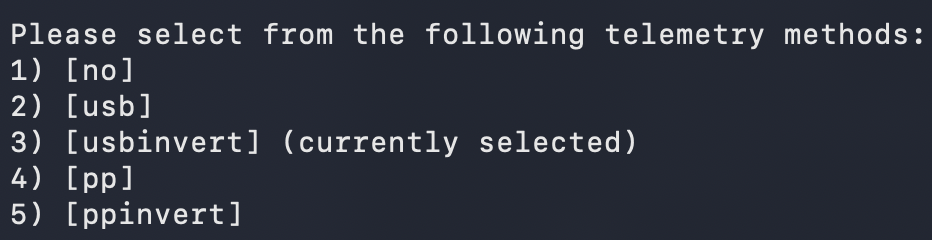
Now it was just a matter of configuring the URI (RIM Lite) to talk to the radios correctly. We weren’t getting the exciter to key up. Using the simpleusb-tune-menu application we were able to set the proper COSFROM settings to get the controller (the Pi) talking to the radios by switching from usb to usbinvert.
So we pull up the COS, CTCSS and PTT Telemetry in realtime. As Steve keyed his HT, I watched for COS. Nothing on showing up on the telemetry, so we powered everything down, thinking that maybe we had the Y-cable hooked up backwards (1 side had red shrink tubing, 1 side had blue shrink tubing), and Steve flipped the cable around. We powered everything up again, pulled up the telemetry, and keyed up.
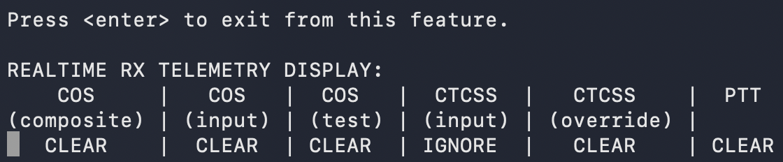
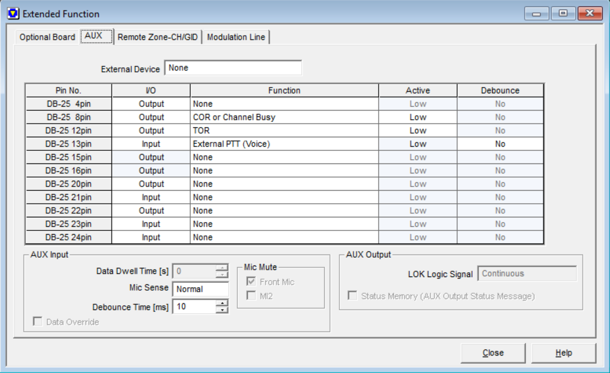
We still weren’t seeing anything on the telemetry for COS, so we went through the power off sequence again (graceful shutdown of the controller) to switch the Y-cable back around. Steve reached out to Tim via text to find out we could get a copy of the programming software and the code plug. We also inquired if Scott and Tim had done any configuration of the AUX ports that the interface cable connected to. It wouldn’t be until the next day that we would find out that we were missing some of the settings for setting required for getting the radio talking to the RIM.
In the meantime, I gave the Supermon header a little bit of a facelift, and made sure that it clearly identified which repeater it belonged to. Since we have several repeaters backed by HamVOIP and Supermon, having the location, band, and club branding right up front makes it a lot easier to know exactly what system you are looking at. It was not a major technical change, but it did give the controller a little bit of flash and made the monitoring page feel a little more like “ours.”

After the missing AUX port settings were sorted out in the Kenwood programming, everything finally started behaving the way we expected. The controller was seeing the receiver, the exciter was keying, and the pair of TK-8180s were doing exactly what we needed them to do. What started as an unexpected failure of the old DR-1X turned into a full rebuild using equipment, parts, and knowledge from several members of the club.
And here is the final product: the new Lancaster Amateur Radio Club UHF repeater, built around a pair of Kenwood TK-8180 radios, a RIM Lite interface, and a Raspberry Pi running HamVOIP. It may not have the C4FM and WIRES-X features of the Yaesu, but it gets us back on the air with a solid analog 70cm machine. If you’re in the Buffalo, NY area you can find the repeater on 443.850 MHz, positive offset, PL 107.2 Hz.